|
Danish
Audio
ConnecT CT1 Audio Attenuator
Reviewed
by Fred Gloeckler
The
Danish Audio ConnecT (DACT) CT1 Audio Attenuator is a compact, 24-step
switched attenuator.
It
uses surface mount (SMT) resistors In a series configuration and
is available in one (mono unbalanced), two (stereo unbalanced or mono balanced),
and four (stereo balanced or quad unbalanced) deck configurations (Photo
1).
It
offers standard controls with total resistances of 10, 20, 50 and 100k
Ohm. Custom versions will be considered.
The
nominal attenuation at each of the 24 steps is: 0, -2, -4, -6, -8, -10,
-12, -14, -16, -18, -20, -22, -24, -26, -28, -30, -32, -34, -38, -42, -46,
-50, -60 and -infinite dB.
The
SMT resistors are soldered to a circuit board, which, in turn, is soldered
directly to the switch deck pins. The layout is very compact, and is said
to minimize inductance and stray capacitance. Both the circuit board and
switch contacts are gold-plated. The switch source appears to be ELMA.
Figure
1 shows the outline dimensions of the two-deck version (also see Photo
2). 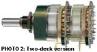
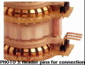
The
front of the switch has a locating tab that fits in the notch in the mounting-panel
hole. The header pins allow you to make connections by hardwire, a header
socket, soldering to a circuit board, or, I suppose, a wirewrap (Photo
3). 
The
CT1 takes up little panel space and is suited for "slim-line"enclosures
that can't accommodate larger switches or potentiometers. Danish Audio
ConnecT's model CT2 (not tested) is slightly more compact.
The
switch has a positive mechanical detent at each step. While the turning
torque is light, the detents can be felt and heard.
The
6mm-diameter shaft accommodates knobs with standard 0.25" shaft holes.
If panel space is at a premium, you can use a relatively small-diameter
knob and still turn the shaft without using excessive force.
Danish
Audio ConnecT has a comprehensive data sheet for the CT1. Key electrical
characteristics are listed in Table 1.
| TABLE
1: KEY ELECTRICAL CHARACTERISTICS |
|
|
|
|
| Total
resistance accuracy (new) |
|
|
| DC
attenuation accuracy (new) |
|
|
| DC
matching accuracy (tracking) (2 wafers) |
|
|
|
|
|
| Contact
capacitance (adjacent contacts) |
|
|
| Series
inductance (10kOhm version, pin 1 to 3) |
|
|
| Bandwidth
(10kOhm version, A=-6dB, deltaA=-3dB) |
|
|
| Noise
voltage (10kOhm version, pin 1 to 3) |
|
|
| Total
harmonic distortion (A=-6dB, f=1kHz) |
|
|
You
can find more specifications on the DACT website.
My
shop isn't equipped to confirm many of the electrical specifications. I
checked attenuation accuracy, channel balance, frequency response, and
channel separation with the outputs of a 20kOhm stereo CT1 feeding unity-gain
buffers.
This
setup simulates the loading an attenuator might see in real life. The CT1
was mounted in an aluminum box with its inputs connected to the input jacks
via shielded cable. The attenuator outputs were connected to the inputs
of a pair of Borbely tape buffers1 by short, unshielded wires.
The buffers isolate the attenuator from the loading effects of cables and
test equipment and have a 1MOhm input resistance.
Measurements
Measurements
were made with a Fluke 8050A digital multimeter using the Morrey
version of a Heath IG-18 audio generator as a signal generator³.
In
addition to measuring the control resistance, I measured attenuation for
each control step at frequencies of 1, 10, 20, 50, and 100kHz using the
relative measurement capability of the 8050A. I then analyzed the measurements
to extract attenuation, channel-balance, and frequency-response errors.
The
total resistance errors for the two channels were -0.1% and -0.075%, which
meet the tight specifications.
Because
the CT1's performance is at or better than my instrumentation's
measurement capability, I debated how to present the results, or even,
whether to present them. I finally decided to just list the attenuation,
channel balance, and frequency-response errors tabulated in table 2.
| TABLE
2: CT1 ATTENUATION ERROR, CHANNEL BALANCE, AND FREQUENCY RESPONSE |
|
|
|
|
|
|
Frequency
Response Error (dB)
|
|
|
|
|
|
|
|
|
|
|
|
|
|
|
|
|
|
|
|
|
|
|
|
|
|
|
|
|
|
|
|
|
|
|
|
|
|
|
|
|
|
|
|
|
|
|
|
|
|
|
|
|
|
|
|
|
|
|
|
|
|
|
|
|
|
|
|
|
|
|
|
|
|
|
|
|
|
|
|
|
|
|
|
|
|
|
|
|
|
|
|
|
|
|
|
|
|
|
|
|
|
|
|
|
|
|
|
|
|
|
|
|
|
|
|
|
|
|
|
|
|
|
|
|
|
|
|
|
|
|
|
|
|
|
|
|
|
|
|
|
|
|
|
|
|
|
|
|
|
|
|
|
|
|
|
|
|
|
|
|
|
|
|
|
|
|
|
|
|
|
|
|
|
|
|
|
|
-18
|
-0.05
|
-0.06
|
-0.01
|
-0.01
|
0.01
|
0.02
|
0.01
|
-0.01
|
-0.03
|
-0.01
|
0.09
|
-0.01
|
-0.01
|
0.02
|
0.11
|
|
-20
|
0.01
|
0.01
|
0.00
|
0.00
|
0.01
|
0.02
|
0.02
|
0.01
|
0.00
|
0.01
|
0.01
|
0.01
|
0.01
|
0.03
|
0.03
|
|
|
|
|
|
|
|
|
|
|
|
|
|
|
|
|
|
|
|
|
|
|
|
|
|
|
|
|
|
|
|
|
|
|
|
|
|
|
|
|
|
|
|
|
|
|
|
|
|
|
|
|
|
|
|
|
|
|
|
|
|
|
|
|
|
|
|
|
|
|
|
|
|
|
|
|
|
|
|
|
|
|
|
|
|
|
|
|
|
|
|
|
|
|
|
|
|
|
|
|
|
|
|
|
|
|
|
|
|
|
|
|
|
|
|
|
|
|
|
|
|
|
|
|
|
|
|
|
|
|
|
|
|
|
|
|
|
|
|
|
|
|
|
|
|
|
|
|
|
|
|
|
|
|
|
|
|
|
|
|
|
|
|
|
|
|
|
|
|
|
|
|
|
|
|
|
|
|
|
|
|
|
|
|
|
|
|
|
|
|
|
|
|
|
|
|
|
|
|
|
|
|
|
|
|
At
the specified level of attenuation accuracy, the loading of a 1MOhm resistor
on a 20kOhm control is significant. Therefore, I compensated attenuation
measurements for the buffer input resistance.
Most
of the attenuation errors at 1kHz were well within the 0.05dB limit, specified
at DC. Those that exceeded the limit I attribute to measurement error rather
than a deficiency in the CT1.
In
any case, the audible result of attenuation error is an incorrect setting
of the system output level. Step size and finite loading of the attenuator
are likely to dominate the ability to establish the desired level, rather
than the insignificant errors indicated by the measurements.
The
channel balance (tracking between the two decks) was well within the specified
0.05dB at frequencies up to 50kHz.
You
should not experience any "image wander" when the control position is changed.
The
frequency-response errors at 10, 20, 50, and 100kHz are relative to the
output at 1kHz and are inconsequential throughout the audible range. The
larger errors at higher frequencies and high attenuation definitely result
from the 8050A's measurement limitations rather than any deficiencies in
the CT1.
Figure
2 shows
the separation, relative to the output of the driven channel, at -10dB
attenuation with approximately 1.5V RMS out of the driven channel.
The
nondriven input was terminated with a 150Ohm resistor to simulate source
output resistance. The least separation occurred around -10dB attenuation.
Some
experimentation indicated that application of shielding might improve the
separation figures a couple of dB. Since the results were excellent without
shielding, I didn't pursue it further. If you take care with the layout
of the ancillary circuitry, the CT1 shouldn't audibly degrade separation.
Listening
Tests
For
listening tests, I mounted the CT1 in an aluminum enclosure and directly
wired it to gold-plated pairs of RCA-style input and output jacks. The
buffers used for the instrumented tests were not used except for
a brief listen. I used a 20kOhm Alps "black" pot, which was several years
old, and my "passive preamp" for comparison.
The
Alps pot was configured the same as the CT1. The "passive preamp" has 32-step,
dual-concentric series attenuator; a 20dB "mute" switch; and extensive
input and tape-recorder selection switching. The dual-concentric control
was built a number of years ago with 2% carbon-film resistors and Shallco
silver contact switches. The "passive preamp" jacks are not gold-plated.
I
auditioned commercial CDs and master DATs of some of my own recordings.
The system front end consisted of a Rotel RCD-955AX CD player or TASCAM
DA-30 MkII DAT recorder, used as transports, feeding an Assemblage DAC
1.5. Since my DATs were recorded middle-side (M-S) with a crossed
figure-8-pattern stereo microphone, the DAC fed a homebrewed M-S dematrixer
only for the tapes. A partially "pooged" Hafler DH200 amplifier fed IMF
Studio III-B speakers. While not state of the art, the system has a reasonably
natural sound.
Since
it had the coarsest level of resolution, I first chose the listening level
using the CT1. The other two controls were then set to give the same level
out of the amplifier at 300Hz. Since the "passive preamp" was designed
for the load of the amplifier and the CT1 wasn't, the output was 0.17dB
lower with the "passive preamp" at the closest setting.
The
Alps pot wasn't competitive with either the CT1 or the "passive preamp".
A
DAT of Stravinsky's Pulcinella Suite provides a wide range of instrument
combinations and colors. The Alps pot imparted a significantly colored,
"hollow" sound to the ensemble, with no sense of "air".
A
CD of Maurice Durufles organ music (Hyperion CDA66368) has a great dynamic
range, a variety of organ colors, and some wind and "room" sounds. In the
first cut, there is a quiet section with a mixture adding brightness. With
the Alps pot, I couldn't hear the fundamentals, and the mixture sounded
pretty much of a hash. There wasn't much sense of the room or the wind
noises at the end of the cut. I didn't invest more time with the Alps pot.
Natural
Sounds
With
the Stravinsky, the CT1 had very natural instrument sounds with a good
sense of space. The harmonics were well integrated with the fundamentals.
In comparison, the "passive preamp" had a somewhat darker sound, with less
sense of the room.
The
sound was bound more to the speakers, and the harmonics were less well
integrated. With the Durufle´ selection, there was clearer definition
of the organ's voices, better sense of the space (and wind noises), and
better integration of fundamentals and harmonics with the CT1.
A
CD by the BBC Singers (BBC MM125) revealed some interesting contrasts.
In Bach's Der Geist Hilft (BWV 226), the singers were clearer, and
the continuo organ more distinct and rhythmic with the CT1. This cut has
a lot of what I call "splatter echo", and I surmise the recording venue,
St. Paul's Church, Knightsbridge, London, has hard surfaces. Anyway, the
"splatters" were more distinct with the CT1 and more in keeping with my
experience in similar acoustics.
In
a piece by Max Reger, the CT1's sound was less dark and more natural. In
the loud parts, the chorus sounded more intense and involved than with
the "passive preamp." In some songs by Mendelssohn, the micro dynamics
were more evident and the choir less bound to the speakers when the CT1
was used.
In
a recording of our church choir with organ and string orchestra, more individual
singers were recognizable and there was better separation of voices and
instruments through the CT1. I could go on but, you get the picture - the
CT1 was simply clearer than the "passive preamp". This wasn't accomplished
by the addition of artificial detail. The components of the sound were
better integrated and closer to life.
In
comparison, the "passive preamp" interjected a slight brownish haze that
obscured detail. By the way, when the buffers were added to the equation,
the sound was excessively bright and unattractive. It reemphasized the
reasons I haven't had a line stage in my main system for 25 years.
With
its clear, natural sound, superb specifications, compact size, and high
quality standard, I highly recommend the CT1 for consideration when you
need a volume control. After listening to it, I'm compelled to upgrade
my system. Now, if they'd just provide a high-resolution means to adjust
balance...
References
1.
Erno BorbeIy, "The Borbely Preamp, Part II," TAA 1/86.
2.
Fred Gloeckler, "Fluke 805OA Digital Multimeter," TAA 1/82.
3.
Walter T. Morrey, "Morreys Super Oscillator," TAA/4/75
4.
Walt Jung and Dick Marsh, "POOGE-2, A Mod Symphony for Your Hafler DH2OO
or Other Power Amplifiers," TAA 4/81. |
Manufacturer's
response:
We
wish to thank Audio Electronics and Fred Gloeckler for the thorough
review of our CT1 stepped audio attenuator. One detail to add is that the
CT1 is now also available in 250kOhm and our CT2 attenuator is also available
in 500kOhm. Since the review appeared, we also have changed our policy
to include in our prices the shipping costs worldwide. The new prices (in
US dollars) are: CT1 mono, $113; CT1 stereo, $154; CT1 balanced stereo,
$284.50; CT2 stereo, $136; and CT2 A/V audio 6-channels (new item), $319.
We
appreciate the care that Mr. Gloeckler has taken when considering the measurements
and their validity.
The
CT1 matches most test equipment on many parameters, and it is of
course important to evaluate the measurements' validity. Well done!
We
have also concluded, like Mr. Gloeckler, that the sonic performance of
a high-quality passive volume control is often better than most active
preamplifiers. This may not come as a surprise, since all components add
their own signatures to the sound, and only the finest preamplifiers are
nearly "inaudible."
On
the other hand, connecting, for example, a CD player directly to the power
amplifier with only a passive volume control in between has its own limitations.
Some important impedance issues need to be considered. At our web site
there is an application note describing this topic.
Both
passive and active preamplifiers require a high-quality volume control
and we are satisfied that Mr. Gloeckler's listening tests document that
there are significant audible differences between standard volume controls
and the more specialized controls.
ln
his review, Fred Gloeckler caIls for a high-resolution balance control.
We will not disappoint him. We are now working on a stepped balance control
with very high resolution.
Allan
Isaksen
Danish
Audio ConnecT, Ltd. |